

What Is The Circuit For A Disposable Camera Flash

1.5 Volt Strobo with a
Kodak Max Disposable Camera
past Le Magicien
This articles shows how to modify the flash circuit that comes with a cheap Kodak Max Disposable Photographic camera in club to use it every bit a low frequency strobe.

These cameras are disposable, which means that photoprocessing labs throw them away after film extraction, so y'all have for free these useful and totally functional flash circuits for your projects !!! (sometimes they dispose the cameras with the i.5 volt element of group i bombardment within).
Inside this photographic camera at that place is this handy wink unit which we were talking about; the nice matter is it works on a 1.5 volt alkaline battery, what makes this circuit very useful in a variety of low power application. So next time ask the processing lab if they can go along the disposable cameras for yous !!!
OPENING THE Photographic camera
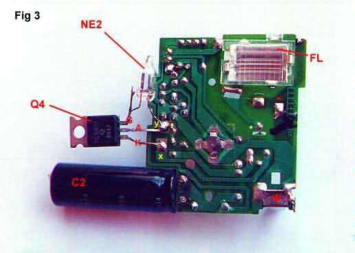
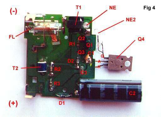
With the camera opened yous'll find a circuit board very similar to the photographs shown below; carefully, remove the circuit from the camera while taking annotation of battery polarity and shutter metallic contacts (these contact will shut during the exposition in order to trigger the wink).
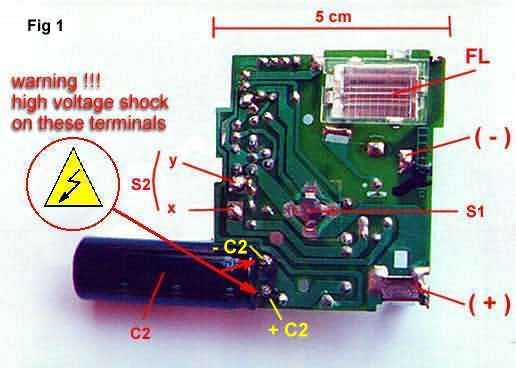
FL : Flash Lamp with reflector and protection hat
S1 : Charge Start push button
(+) (-) : 1.5 volt alkaline battery contacts
C2 : 160 uF/350 volt electrolytic capacitor
S2 : shutter contacts - triggers flash when terminals ten and y are short-circuited

T1 : Step up transformer (ane.v/350 ratio frock)
T2 : Trigger coil - HV trigger to ignite FL
NE : Neon Lamp (turns on when C2 is charged- flash charge indicator light)
T2 : Trigger coil - HV trigger to ignite FL
for other components see circuit diagram below
Subsequently some "reverse technology" I came with the post-obit excursion for the flash board. Please notation that this unit of measurement has no SMD components, just I've plant newer cameras with them, but the circuit is substantially the same.
I need to desolder D1 and D2 in lodge to properly identify these components, also need to take a closer expect to Q1 transistor type (base bias resistors included inside the transistor example???).
THE STROBO - Circuit Modifications
As I didn't have a SIDAC device with me (information technology triggers when voltage between terminals reaches certain value), I used a SCR and a neon lamp to improvise i, not a perfect solution but it works well.
As y'all may run into between trigger terminals x and y of S2 I've put a SCR (TIC 106M) which is triggered when the voltage betwixt NE2 terminals reaches certain value (aproximately 200 vdc). This ways NE2 is a neon lamp of 200 volts or so (note in fig iii the wide gap betwixt electrodes inside the neon lamp).
The modified circuits is shown below:
Notes
Note that different blazon of neon lamps used in NE2 volition give different triggering voltages, in many cases a value too low will not let the main capacitor C2 to acquire a full charge, perhaps producing no flash at all!!! I used a neon lamp of 200 volts which, I know, is not an easy-to- find component, merely it may be replaced by two or three common NE lamps of 60-80 volts each, wired in series, in order to reach 200 volts or and so.
WARNING: ALSO REMEMBER THAT THE MAIN CAPACITOR C2 (THE BIG One) HAS A Overnice CHARGE STORED INSIDE, IF YOU ACCIDENTALLY Brusque-Circuit ITS TERMINALS WITH YOUR Torso, Y'all'LL RECEIVE A VERY NASTY SHOCK !!! (watch your underwear!!!) Be certain to brusk circuit C2 terminals with a screwdriver earlier excursion handling !
IMPROVED STROBO VERSION- Circuit Modifications
This new version is based on an electronic schematic given in the topic "Converting a Pocket Photographic camera Strobe into a Repeating Strobe" from the wonderful Sam'southward Strobe FAQ page (located at http://world wide web.misty.com/people/don/samflash.html#strbcpp).
The values given in the additional circuit are the actual ones of the working prototype (I used what I had at the moment), just certainly they may be altered without affecting the overall functioning.
- Marking on the circuit the negative (-) and positive (+) terminals of capacitor C2, as seen in Figs 1 & two.
- The original capacitor C2 (photoflash type - normally 120 to 160 microfarads, big black cilinder in Figs 1 to iv) must be removed.
- The additional circuit -ADCIRC-(see schematic below) volition have three connecting terminals: Z1, Z2 and x.
- Terminal Z1 of ADCIRC will exist connected to -C2 terminal of camera flash circuit board; concluding Z2 to +C2 terminal and '10' terminal of ADCIRC to the 'x' terminal of S2 as shown in Fig1.
- The 3 megohm potentiometer in the ADCIRC controls the frequency of the flashes, from a dozen hertz to few flashes per infinitesimal.
- Finally, brusque-circuit switch S1 shown in Fig one (solder a wire between S1 terminals).
Last Review (month/solar day/year)
by LeMagicien

Source: https://pe2bz.philpem.me.uk/Lights/-%20Xenon-Strobes/Lt-207-Strobe-from-KodakMaxDisposible/maxflash.html
Posted by: whiteprodins.blogspot.com
0 Response to "What Is The Circuit For A Disposable Camera Flash"
Post a Comment